Key Takeaways
- Production dies are custom-engineered, heat-treated tool steel molds built for full-volume manufacturing runs.
- Cavity inserts, cores, slides, ejector pins, and cooling channels each directly affect part quality and cycle efficiency.
- Wall thickness, draft angles, parting line placement, and cooling layout are the design decisions that determine long-term die performance.
- Die lifespan varies dramatically by alloy: zinc tooling outlasts brass tooling by a wide margin.
- PVD coatings on hardened tool steel inserts extend run intervals and cut maintenance frequency beyond what steel selection alone can achieve.
What Are Production Dies in Die Casting?
A production die is a precision-machined, multi-part mold manufactured from heat-treated tool steel. The job is straightforward in concept, demanding in execution. It must hold molten metal under pressures ranging from 2,000 to 10,000 psi, allow rapid solidification, and release a near-net-shape part with consistent geometry and surface finish — thousands of times over.
The Two-Half Structure
Every die casting die splits into two halves:
- Cover die — the stationary half, mounted to the casting machine frame, containing the metal-entry path
- Ejector die — the moving half, which opens after solidification and carries the ejection system
During each shot cycle, the halves clamp together under hydraulic force, molten metal fills the cavity, solidification occurs in seconds, and the die opens. The ejector system then pushes the casting free before the cycle repeats.
When Production Dies Are Used
Production dies are not prototyping tools. They enter service only after the part design has been reviewed, approved, and locked. Using a production die for early design exploration wastes both budget and lead time. Committing to a production die signals that the program is ready for volume — and that the part geometry, tolerances, and material spec won't change.
Types of Die Casting Dies
Not every program needs the same tool. Die type selection depends on part complexity, volume expectations, and budget.
Prototype Dies
Prototype dies use standardized components and pre-hardened steels, which reduces both lead time and upfront cost. They suit small quantities — useful when you need dimensional validation or a limited market sample before committing to a full production tool.
Production Dies
Production dies are fully custom-engineered for a specific part geometry, built for long run life in single-cavity or multi-cavity configurations. Slides can be added for parts with undercuts or side features that cannot be formed in the primary draw direction.
Unit Dies
A unit die uses a standard holder — typically owned by the die caster — that accepts a customer-owned cavity block insert. The expensive main frame is reused across multiple programs, which reduces cost for smaller, lower-volume parts. When part size and volume fit within the holder's constraints, unit dies are worth evaluating before committing to a full production tool.
Trim Dies
Trim dies work alongside production dies in high-volume operations. After casting, the part exits with runners, overflows, and flash still attached. A trim die removes all of this automatically to maintain throughput. Key factors that drive trim die complexity and cost include:
- Parting line geometry (more complex lines require more tooling stages)
- Multi-station configurations for high-feature parts
- Hydraulic actuation for tighter flash removal tolerances

Anatomy of a Production Die: Key Components
Understanding what a production die is made of makes it much easier to evaluate design decisions, cost drivers, and maintenance needs.
Cavity Inserts
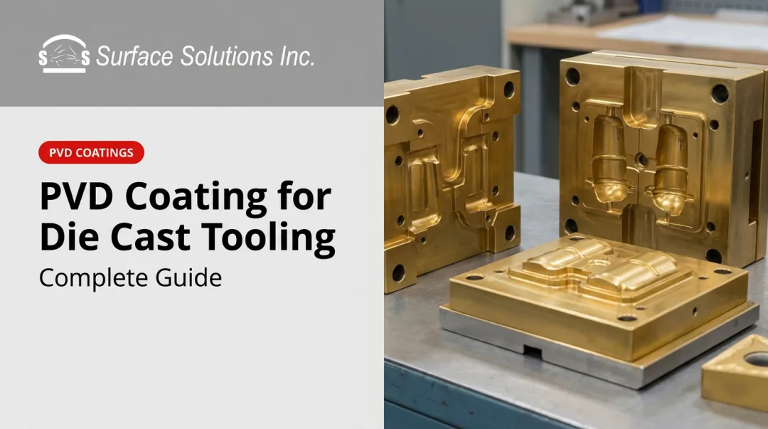
The cavity inserts are where part geometry is formed. The cover cavity and ejector cavity together define every surface the casting touches. These inserts are machined from hardened tool steel, heat-treated to high hardness, and coated before production begins.
Cooling channels pass directly through the blocks to manage die temperature each cycle. Because cavity inserts require custom engineering and precise machining for every program, they represent the largest portion of total die cost.
Parting Lines
The parting line is the seam on the finished casting where the two die halves meet. Its placement affects cosmetic appearance, flash quantity, and dimensional accuracy. Choosing the parting line location is one of the first and most consequential decisions in die design — a poorly placed parting line creates downstream trimming problems and can affect how the casting functions in its assembly.
Cores and Core Pins
Cores form internal features — holes, pockets, recesses — that cannot be created by the main cavity halves alone. Three types exist:
- Fixed cores — oriented parallel to the pull direction, no additional actuation required
- Movable cores — require separate mechanical or hydraulic actuation to withdraw before die opening
- Loose cores — hand-inserted before each shot, used for complex threaded or irregular features
Movable and loose cores each add cost and extend cycle time. They should be used where the part geometry demands it, not as a default approach.
Slides
Slides are moving die sections that form undercuts, side holes, or features that cannot be pulled in the primary open/close direction. Two actuation methods are common:
- Angle-pin slides — mechanically driven by the die opening motion, economical, limited stroke
- Hydraulic slides — independently timed, capable of longer travel, more flexible for complex sequences
Every slide adds engineering complexity. Programs with multiple slides require careful sequencing — timing errors between slides can cause interference during the shot cycle, damaging the die or stalling production.

Ejector Pins and Ejector Plate
After solidification, the casting clings to the ejector half. Ejector pins — driven simultaneously by an ejector plate — push the part free with equal force across all pin locations. Pin placement matters because each pin leaves a small witness mark on the casting surface. Acceptable target locations include:
- Overflow tabs and runner gates
- Boss tops and rib bottoms
- Deep pocket floors
- Non-cosmetic faces away from mating surfaces
Pin count, diameter, and layout are determined by part weight and geometry.
Production Die Design Considerations
Design decisions made before steel is cut determine how the die performs for its entire service life.
Wall Thickness and Ribs
NADCA notes there are no hard-and-fast rules for minimum or maximum wall thickness, but consistent wall thickness is consistently recommended. Abrupt transitions between thick and thin sections create turbulence during fill and shrinkage defects during solidification. Where structural support is needed, ribs are the preferred solution — they add rigidity without creating heavy masses. Sections that are at least twice the thickness of most of the casting should be cored out or redesigned rather than accepted as-is.
Draft Angles
Every surface parallel to the die opening direction needs a taper — called draft — to allow clean ejection. Draft requirements vary by alloy, feature depth, and whether the surface is an outside wall or an inside wall that the metal shrinks onto. NADCA recommends roughly twice the draft on inside surfaces because of this shrinkage effect. Insufficient draft causes part damage, accelerates die wear, and increases ejection force on every cycle.
Cooling Channel Design
Cooling channels routed through cavity inserts and slides do more than reduce cycle time — they control temperature distribution across the die face. Uneven cooling causes warping, porosity, and dimensional inconsistency. A 2022 H13 fatigue study found that aggressive copper-plated conformal cooling, despite faster temperature reduction, created greater thermal gradients that led to die fracture near 10,000 cycles — significantly shorter than straight-channel and unplated conformal alternatives. Channel spacing and material selection should prioritize consistent temperature distribution across the die face over raw cycle speed.
Single-Cavity vs. Multi-Cavity Configurations
Multi-cavity dies produce multiple identical parts per shot, which improves throughput and reduces per-part cost at volume. The trade-off is higher engineering complexity and greater upfront tooling investment. Three factors determine whether multi-cavity makes economic sense:
- Part geometry — complex shapes increase cavity cost and flow balancing difficulty
- Annual volume — higher volumes spread tooling investment across more parts
- Machine tonnage — multi-cavity tools require larger presses to maintain fill pressure
Early Design-for-Die-Casting Collaboration
Changes to a hardened production die are expensive and slow. Modifications that would take hours on a prototype tool can take weeks and thousands of dollars on a finished production die. Involve the die caster before design is locked — at minimum, align on:
- Functional requirements — load paths, interfaces, and critical features
- Cosmetic zones — which surfaces require class-A appearance vs. structural only
- Tolerances — achievable vs. desired, to avoid downstream rework
- Volume targets — tool steel grade and cavity count depend on production life expectations
Die Materials and Tool Steel Selection
Steel Grades by Alloy
Cavity insert steel selection starts with the alloy being cast and the thermal severity it imposes. Uddeholm's die casting reference gives representative molten metal temperatures that explain why alloy choice drives steel choice:
| Alloy | Representative Melt Temperature | Typical Steel Grades |
|---|---|---|
| Zinc | ~420°C | P20 and similar softer grades |
| Magnesium | ~650°C | H11, H13 hot-work steels |
| Aluminum | ~700°C | H11, H13 hot-work steels |
| Copper/Brass | ~970°C | Higher-alloy grades (DIN 1.2367) |
For aluminum and magnesium, H13 and H11 are the standard choices. Zinc's lower thermal severity permits softer grades like P20, which Bohler-Uddeholm's datasheet explicitly lists for zinc die casting applications. Copper and brass demand grades engineered for greater hot strength and temper resistance given their far higher casting temperatures.
Hardness selection is not simply "higher is better." Higher hardness improves wear resistance but reduces toughness — a die that is too hard for its geometry risks gross cracking rather than gradual wear. Steel makers publish grade- and component-specific heat treatment tables. Use those specifications — not generic ranges — as the hardness target.
Die Failure Modes
A 2023 Journal of Materials Processing Technology study found that thermal fatigue cracks account for approximately 70% of scrapped die casting molds. ASM identifies three primary failure mechanisms:
- Erosion — progressive material loss from high-velocity molten metal at gates and runners
- Heat checking — a network of shallow surface cracks caused by repeated thermal cycling each shot
- Thermal fatigue — cumulative crack growth that accumulates over the die's service life

Die lifespan is not a fixed number. It depends on alloy temperature, part geometry, die size, steel grade and cleanliness, hardness, cooling layout, lubrication, and maintenance practices. Zinc's lower casting temperature imposes far less thermal stress per cycle, so zinc tooling outlasts brass tooling by a wide margin.
Extending Production Die Life
Lubrication and Release Agents
Water-based die lubricants dominate aluminum and magnesium HPDC for good reason: the water carrier evaporates on contact with the hot die surface, cooling it rapidly, while the active release compounds deposit a film that prevents the casting from adhering. Water quality matters more than many operators expect — mineral deposits from untreated dilution water can destabilize the release film and accelerate surface degradation over time.
Preventive Maintenance
Scheduled inspection is less expensive than emergency repair. Regular checks for heat checks, gate erosion, ejector pin wear, and cooling flow changes allow maintenance teams to address minor damage before it propagates into deep cracking or dimensional drift. The right maintenance interval is condition-based — set from observed trends, not a universal shot count.
Die Repair and Welding
Minor erosion and shallow heat checks can often be addressed by welding and re-machining the affected cavity area. Uddeholm notes that repair welding always carries cracking risk, though good results are achievable when proper preheat, filler selection, and controlled cooling procedures are followed. Repair extends service life; it does not restore a die to guaranteed new-die condition.
PVD Coatings
Physical vapor deposition coatings applied to cavity inserts, cores, and slides add a hard, low-friction surface layer that works independently of the base steel. A 2019 Die Casting Engineer paper identifies CrN and related PVD systems as effective barriers against aluminum soldering on die steel — one of the more persistent problems in aluminum HPDC.
Surface Solutions, based in Fridley, Minnesota, applies CrN and AlTiN coatings to hardened tool steel components for die casting and other demanding manufacturing applications. Coatings are deposited at approximately 700°–800°F and measure 0.0001″–0.0002″ (2–5 microns) thick — thin enough to preserve dimensional fits, yet hard enough to change surface performance meaningfully.
AlTiN is listed among Surface Solutions' die casting applications specifically for its hardness and high-temperature oxidation resistance.
Before sending cavity inserts for PVD coating, two preparation steps are non-negotiable:
- Remove EDM recast layers — coatings will not adhere to recast material and will fail in service if applied over it
- Finalize surface finish first — PVD coatings replicate the substrate surface faithfully and will not correct a rough or uneven finish

Die casting facilities across North America can reach Surface Solutions at 763-785-9436 or info@tincoat.net to discuss components and coating selection.
Shot Count Monitoring
Tracking cumulative shots against material-specific maintenance benchmarks allows production teams to plan downtime rather than react to it. Shot count data also creates a usable history: as patterns emerge across tool steel grades and part geometries, teams can refine benchmark intervals rather than applying generic targets across every die in the shop.
Frequently Asked Questions
What are dies in die casting?
Dies are precision-machined, hardened tool steel molds consisting of a stationary cover die and a moving ejector die. Molten metal is injected under high pressure into the cavity formed when both halves clamp together. The die defines the part's geometry, surface finish, and dimensional accuracy.
What is the lifespan of a die casting mold?
Die lifespan depends on alloy type, steel grade, cooling design, and maintenance practices. Zinc tooling runs at lower thermal severity and typically outlasts aluminum dies; brass dies face the highest thermal loads and have the shortest service lives. Where any specific die falls within that range comes down to geometry and how consistently it's maintained.
What is the difference between a prototype die and a production die?
Prototype dies use standardized components and pre-hardened steels for lower cost and faster lead time, suited for small validation quantities. Production dies are fully custom-engineered and hardened for long run life and maximum efficiency — they enter service only after a design is finalized and approved for volume manufacturing.
What materials are used to make production die casting dies?
Cavity inserts for aluminum and magnesium casting are most commonly made from H13 or H11 hot-work tool steels. Zinc casting permits softer grades like P20. Higher-temperature alloys such as copper and brass require higher-alloy grades engineered for greater hot strength, such as DIN 1.2367.
What causes die casting die failure?
The three primary failure modes are erosion from high-velocity metal injection at gates and runners, heat checking from repeated thermal cycling each shot, and thermal fatigue accumulating over the total cycle count. Thermal fatigue cracks account for approximately 70% of scrapped molds.
How can you extend the life of a die casting die?
Four strategies consistently extend die life:
- Maintain proper lubrication and temperature control each cycle
- Schedule preventive maintenance before minor damage propagates
- Perform weld repair on heat checks using qualified procedures
- Apply PVD surface coatings to reduce soldering, lower ejection friction, and extend maintenance intervals