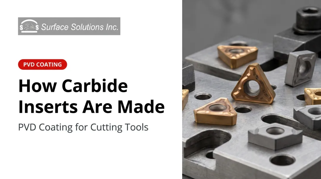
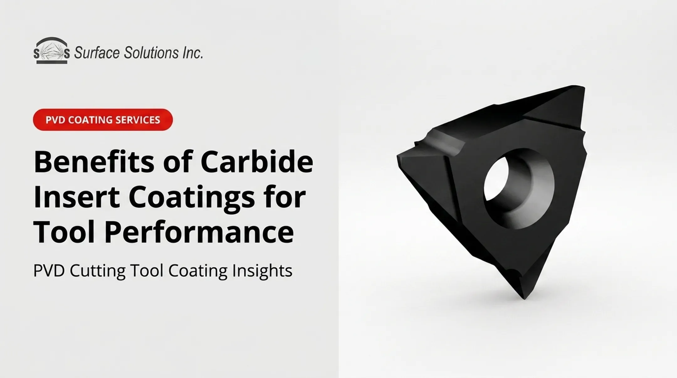
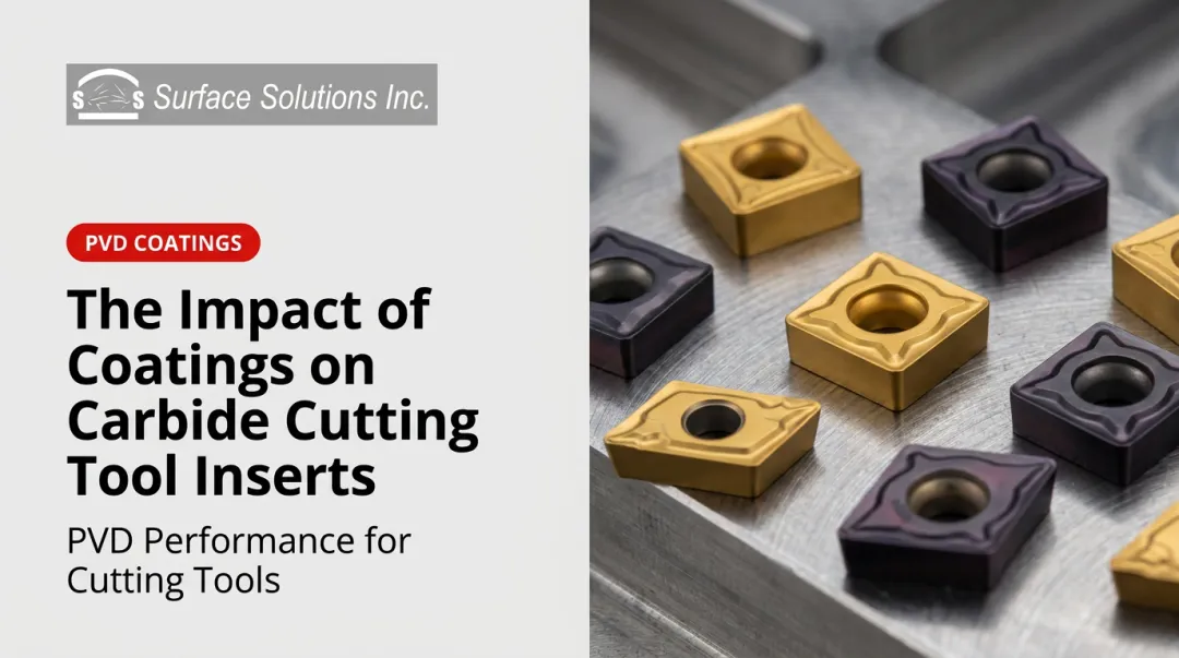
PVD (Physical Vapor Deposition) coated carbide inserts are a specific class of coated tooling where a thin, hard film—typically 2–5 microns—is deposited onto the carbide substrate through a vacuum-based physical process. The result is a sharper, tougher, more wear-resistant cutting edge.
This guide covers what you need to know to make informed decisions about PVD coatings: how the process works, how PVD compares to CVD, which coating types suit which materials, and how to adjust your cutting formulas when switching to PVD-coated inserts.
Key Takeaways
- PVD coatings are 2–5 microns thick, applied at low temperatures, and preserve sharp cutting edges
- PVD and CVD serve different operations—using the wrong one reduces tool life significantly
- Switching from CVD to PVD means lower cutting speeds but better edge toughness and surface finish
- TiN, TiCN, AlTiN, and CrN each have distinct hardness and thermal properties for specific workpiece materials
- PVD-coated carbide inserts can be stripped, resharpened, and recoated to fully restore cutting performance
What Is PVD Coating on Carbide Inserts?
PVD stands for Physical Vapor Deposition—a vacuum-based process where metal compounds are physically vaporized and deposited onto the carbide substrate as a thin film. Unlike electroplating or thermal spraying, PVD does not rely on a chemical reaction to form the coating.
How the Process Works
Inside a vacuum chamber, a metal source (such as titanium or chromium) is vaporized—typically by arc evaporation or sputtering—and reacts with a gas like nitrogen to form a hard compound such as TiN or CrN. That compound then condenses onto the tool surface as a dense, adherent film.
According to a 2022 review in Surface and Coatings Technology, PVD hard coatings on cutting tools are typically 3–5 microns thick, with fracture stress values ranging from 2.7 GPa for TiN up to 5.3 GPa for TiAlSiN.
Key characteristics of PVD coatings:
- Thickness: 2–5 microns (does not meaningfully alter insert dimensions or tolerances)
- Deposition temperature: 700°–800°F (approximately 370°–425°C)—well below the degradation threshold of carbide substrates
- Residual stress: Compressive, generated by ion bombardment during deposition
- Colors: Gold (TiN), black/blue-black (AlTiN), gray (TiCN)—color also serves as a practical wear indicator
Why Low Temperature Matters
Because PVD is applied at temperatures the carbide substrate can tolerate without softening, the insert's core hardness and geometry are fully preserved. Sharp edges remain sharp. Fine honing stays intact. This is what makes PVD the preferred choice for precision inserts and interrupted cuts.
The compressive residual stress is an added mechanical benefit: it delays fatigue cracking under cyclic loading—the conditions common in milling and interrupted turning.
PVD vs. CVD Coatings: Which Should You Choose?
Choosing between PVD and CVD often determines whether a tool thrives or fails in a given operation. Both deposit hard coatings, but their processes produce meaningfully different results at the cutting edge.
CVD (Chemical Vapor Deposition) grows a coating directly on the substrate through high-temperature chemistry, forming a strong chemical bond. The result is a thicker, well-adhered coating with excellent heat insulation. The tradeoff: high deposition temperatures (800–1,150°C) introduce tensile residual stress and can slightly round cutting edges.
Direct Comparison
| Property | PVD | CVD |
|---|---|---|
| Typical thickness | 3–5 microns | 5–20 microns |
| Deposition temperature | ~400–600°C | ~800–1,150°C |
| Residual stress | Compressive | Tensile |
| Edge sharpness | Preserved | Slightly rounded |
| Crack behavior | Delays fatigue cracking | Tensile stress can propagate cracks under cyclic loads |
| Best for | Interrupted cuts, milling, precision finishing | Continuous high-speed turning, heavy abrasion |

When PVD Wins
- Milling and interrupted cutting operations
- Precision finishing with tight surface finish requirements
- Thin-walled parts or unstable fixturing
- Superalloys, titanium, and stainless steel
- Applications requiring a fine, sharp cutting edge
When CVD Wins
- Continuous turning of gray and ductile cast iron at high speeds
- Dry roughing passes where heat insulation matters more than edge sharpness
- Long-duration turning runs where extra coating thickness delays wear-through
Any interrupted cut—milling, profiling, or threading—favors PVD. If you're running continuous cast iron turning at high speeds with no edge geometry requirements, CVD earns its place. In most carbide insert applications involving mixed materials or precision finishing, PVD is the practical default.
Common PVD Coating Types and Their Properties
Four coating chemistries cover the majority of carbide insert applications. Each has distinct hardness, thermal, and friction characteristics.
Coating Comparison Table
| Coating | Typical Hardness | Max Operating Temp | Friction vs. Steel | Best Applications |
|---|---|---|---|---|
| TiN | ~2,800 HV | ~500°C | 0.5 | General-purpose, mild steels, wear indicator layer |
| TiCN | ~3,000 HV | ~400°C | Lower than TiN | Stainless steel, aluminum, lower-friction applications |
| AlTiN | ~3,500 HV | ~850°C | 0.6 | Dry machining, cast iron, hardened steels, high-speed operations |
| CrN | Moderate | ~700°C | Low | Non-ferrous materials, forming operations, galling resistance |

Hardness values based on Ionbond's 2026 cutting tool coating portfolio for commercial PVD products; values are product-specific, not universal chemistry constants.
Advanced Coatings: TiSiN
Silicon-containing PVD coatings push performance further. Ionbond's TiSiN Hardcut Plus reaches 3,800 HV hardness and withstands temperatures up to 1,100°C—compared to AlTiN's 3,500 HV and 850°C ceiling. These coatings target high-speed dry machining above 850°C, where standard AlTiN reaches its thermal ceiling.
For most production machining environments, TiSiN's added cost and process complexity aren't necessary. Surface Solutions applies TiN, AlTiN, TiCN, and CrN coatings — the four chemistries that handle the practical range of cutting tool and forming applications.
Cutting Formulas for PVD-Coated Carbide Inserts
PVD coatings improve surface conditions at the cutting edge, but they provide less thermal insulation than CVD coatings due to their thinner cross-section. That has direct implications for how you set your cutting parameters.
Core Formulas
Both formulas below are standard for any coated or uncoated carbide insert. The coating type affects the SFM value you target, not the formula itself.
RPM from SFM:
RPM = (SFM × 3.82) ÷ Diameter (inches)
SFM from RPM:
SFM = (RPM × Diameter) ÷ 3.82
Source: Kennametal's engineering calculator
Speed Adjustment When Switching to PVD
| Transition | Cutting Speed Adjustment | Feed Rate |
|---|---|---|
| Uncoated → PVD | Increase (PVD improves wear resistance) | Maintain or slightly increase |
| CVD → PVD (same material) | Reduce (less thermal insulation) | Maintain or slightly increase |
| PVD → higher-performance PVD (e.g., TiN → AlTiN) | Increase toward upper range | Maintain |

Starting point: Begin at the lower-to-mid range of the manufacturer's SFM recommendation for your coating and material combination. Adjust upward based on observed wear patterns as performance data accumulates.
Feed Rate and Depth of Cut
Speed adjustments address only part of the equation — feed rate and depth of cut follow their own rules once you've dialed in SFM.
PVD's lower-friction surface reduces built-up edge (BUE) and promotes more consistent chip formation. This stability supports maintaining or slightly increasing feed rates compared to uncoated carbide.
Critical constraint: Coating type does not change the insert's structural load capacity. Depth of cut must remain within the insert manufacturer's geometry specification — a better coating does not extend the insert geometry's mechanical limits.
Visual Wear Monitoring
PVD's thin, color-bearing layer wears away before the substrate does. Use this as your early-warning system:
- Gold fading on TiN-coated inserts signals approaching end-of-life
- Black coating exposure of lighter substrate on AlTiN inserts is a reliable wear indicator
- Monitor color change first; confirm with optical measurement if needed
Color change is your cue to act. Swapping the insert at first visible fade protects part quality and prevents unplanned downtime — something catastrophic edge failure never allows.
Selecting the Right PVD Coating by Material and Operation
Quick-Reference Selection Guide
| Workpiece Material | Recommended Coating | Reason |
|---|---|---|
| Carbon and alloy steel (milling) | AlTiN or TiCN | Hardness and abrasion resistance |
| Stainless steel (cutting) | AlTiN | High hardness, oxidation resistance; Surface Solutions' own case study shows AlTiN delivers 6× better performance than TiN on 304 SS |
| Stainless steel (forming) | CrN | Low friction, prevents galling—same shop data shows CrN produced 500+ parts vs. 15 with other coatings |
| Aluminum and non-ferrous | CrN | Anti-adhesion properties, low friction |
| Superalloys and titanium | AlTiN (thin) | Oxidation resistance at elevated temperatures |
| Cast iron (milling/interrupted) | AlTiN | Handles interrupted loads; abrasion resistance |

Note: Surface Solutions does not coat aluminum substrates. The CrN recommendation here applies to tools that cut aluminum, not tools made of aluminum.
The Role of Insert Geometry
Sharper edge preparations (minimal or no honing) pair best with PVD coatings—they take full advantage of the coating's geometry-preserving deposition process. Negative rake inserts or heavier edge preparations can work with either PVD or CVD.
No coating chemistry fixes a geometry mismatch. If the insert geometry is wrong for your application, the coating won't save it.
Recoating After Resharpening
Getting geometry right also extends how many times a tool can be reconditioned. PVD-coated carbide inserts and solid carbide tools can be stripped, resharpened, and recoated, restoring performance at a fraction of new tool cost. Ionbond reports 3–12 reconditioning cycles for cemented carbide tools, depending on tool type and geometry.
Surface Solutions provides PVD coating services for carbide inserts and cutting tools, including tools sent in by resharpening shops. Tony Deschenes, owner of Special Tools, Inc., said: "Nearly everything we resharpen gets sent out to Surface Solutions for coatings. His tools are working better than new. It's like night and day."
Tools can be shipped to their Fridley, Minnesota facility from anywhere in the US, Canada, or Mexico. Most of the continental US receives coated tools back within 3 business days via UPS Ground.
Key Performance Benefits of PVD-Coated Carbide Inserts
Oerlikon Balzers reports that a PVD-coated carbide drill produced more than 4,500 holes versus 28 holes for an uncoated drill—a 160-fold improvement under controlled test conditions.
For carbide inserts specifically, Surface Solutions' internal case study on a 3-corner carbide insert cutting 304 stainless steel found AlTiN delivered 6× the tool life of TiN-coated inserts, with no changes to speeds or feeds required.
The Four Primary Benefits
- Extended tool life — Increased surface hardness reduces abrasive and adhesive wear at the cutting edge
- Better surface finish — Lower friction and reduced BUE produce cleaner surfaces, often reducing secondary finishing operations
- Improved chip evacuation — Smoother coating surface helps chips clear the cutting zone consistently
- Reduced lubricant consumption — Lower friction means less heat generation and less coolant needed to manage it

The Productivity Math
Longer intervals between tool changes mean less machine downtime. More consistent performance across an insert's life means fewer scrap parts. The incremental cost of a coated insert versus an uncoated one—often just a few dollars per tool—is typically recovered within the first production run through reduced changeover time and scrap.
Signs of a Coating Mismatch
If you're seeing any of the following, your coating choice may not match the application:
- Rapid crater wear — may indicate insufficient thermal protection (consider CVD for high-speed continuous turning)
- Coating delamination — usually points to surface preparation issues or coating-substrate mismatch
- Excessive heat at the cutting zone — AlTiN or a silicon-containing coating may be needed
- BUE formation on stainless — consider AlTiN or TiCN with lower friction coefficient
Each symptom points to a specific fix. Swap the coating type or adjust geometry, then re-run under the same conditions to confirm improvement.
Frequently Asked Questions
What is PVD coating on inserts?
PVD coating on carbide inserts is a thin, hard surface layer (typically 2–5 microns) deposited through a physical vapor process inside a vacuum chamber. It increases surface hardness, reduces friction, and extends tool life without altering insert geometry or edge sharpness.
Which is better, PVD or CVD?
Neither is universally superior. CVD excels in high-speed continuous turning with heavy abrasion, where coating thickness and heat insulation matter most. PVD is the better choice for interrupted cuts, milling, precision finishing, and applications requiring a sharp cutting edge. Operation type drives the decision.
How long does PVD coating last on steel?
Durability depends on coating type, cutting speed, feed rate, and workpiece hardness. Monitor the color layer as a wear indicator: gold fading on TiN or substrate exposure on AlTiN means the insert is near end-of-life. Replace it before reaching the substrate to protect part quality.
What cutting speed should I use with PVD-coated carbide inserts?
Start at the lower-to-mid range of the manufacturer's SFM recommendation for your coating and material. PVD provides less thermal insulation than CVD, so running at the top of the speed range increases the risk of premature wear. Optimize upward incrementally based on actual wear observations.
Can PVD-coated carbide inserts be recoated after resharpening?
Yes. Most PVD-coated solid carbide tools and inserts can be stripped, resharpened, and recoated to restore original performance, with industry data supporting 3–12 reconditioning cycles depending on tool type. Surface Solutions provides this service for cutting tools shipped in from across the US, Canada, and Mexico.
Which PVD coating is best for stainless steel?
Surface Solutions' own case study data points to AlTiN as the top performer for stainless steel cutting—delivering 6× the tool life of TiN on 304 SS with no changes to machining parameters. For stainless steel forming applications, CrN is the preferred choice due to its low friction and resistance to galling.